
In precision manufacturing, the cost of a part is determined not when the machine starts cutting, but when the design is finalized. At KaiSpeed, we’ve analyzed thousands of RFQs and discovered a hard truth: 80% of production cost is locked in during the design phase.
For engineers, procurement managers, and product VPs, reducing CNC machining costs isn’t just about negotiating with suppliers. It’s about speaking the language of the machine tool. Every unnecessary tight tolerance, every deep pocket, and every sharp internal corner adds zeros to your invoice.
This guide bypasses generic advice. We’re diving into the factory-floor reality of Design for Manufacturability (DFM) to help you produce functional, high-quality parts while keeping your budget in check. Here are 9 proven design strategies from KaiSpeed’s machining experts.
Why CNC Parts Get Expensive (Hint: It’s Not Just Material)
Before optimizing your design, you must understand what drives cost in a 3-axis or 5-axis CNC environment. If you can eliminate these cost drivers at the CAD stage, you don’t just save money—you drastically reduce lead times.
| Primary Cost Driver | Why It Inflates Your Invoice | KaiSpeed’s Engineering Solution |
|---|---|---|
| Complex Geometry | Requires 5-axis setups, specialized fixtures, and multiple setups. | Design for 3-axis machining; split complex monolithic parts into bolt-together assemblies. |
| Tight Tolerances | Demands slower feeds/speeds, specialized tooling, and higher scrap rates. | Only tolerance critical functional features; leave the rest at ISO 2768-mK standard. |
| Deep Cavities | Requires long-reach tooling prone to chatter and tool deflection. | Keep depth-to-diameter ratios under 4:1; consult us on undercuts. |
| Manual Deburring | Edge breaks often require secondary manual labor if not specified. | Specify “broken edges” or chamfers in the CAM to automate finishing. |
1. The Golden Rule: Limit Depth-to-Diameter Ratios
End mills are rigid beams, but they vibrate. When machining a deep cavity, the cutting tool flexes. To prevent tool breakage and excessive chatter, the machine must slow down significantly.
The DFM Target: Keep pocket depths less than 4x the end mill diameter.
- Good: A 0.5″ deep pocket with a 1/8″ cutter (4:1 ratio).
- Bad: A 1.5″ deep pocket with a 1/8″ cutter (12:1 ratio)—expect slow speeds, compromised surface finish, and a higher scrap rate.
If deep slots are unavoidable, design them with a generous internal corner radius to allow for a larger, stiffer tool, or contact KaiSpeed’s team to discuss EDM (Electrical Discharge Machining) as an alternative for extreme depths.
2. Add Internal Fillets—Machine Shops Aren’t Chisels
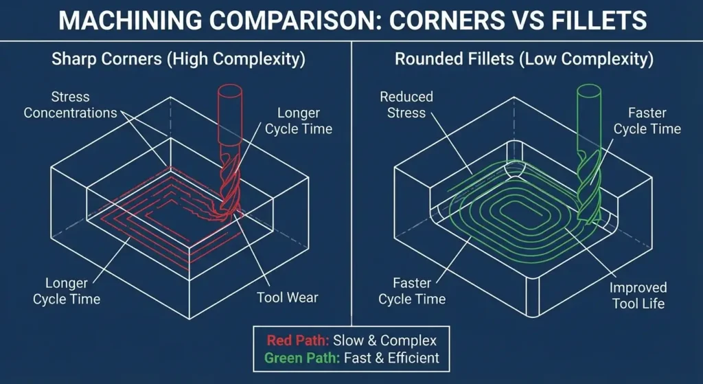
A sharp 90-degree internal corner is physically impossible to create with a rotating round tool. If your design requires a sharp corner, you’re forcing the shop into expensive, slow processes like broaching, EDM, or manual filing.
The KaiSpeed Standard:
- Floor Radius: Always add a fillet where a vertical wall meets the floor. A radius of 0.5mm (0.020”) or more prevents catastrophic end mill failure.
- Corner Radius: Ensure the internal corner radius matches a standard tool size. Increasing a corner radius from 0.5mm to 1.5mm can slash cycle time by 40% by allowing a faster, larger tool to clear the area.
3. Avoid Deep Hole Drilling (Aim for 10x Diameter)
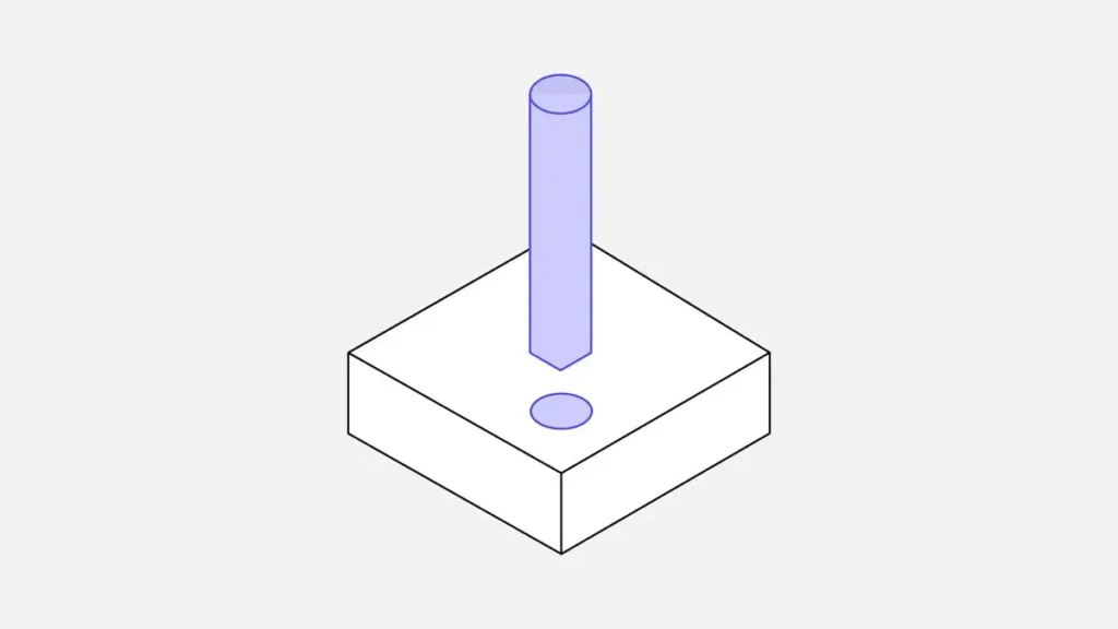
Drilling holes deeper than 10-12 times the drill diameter becomes complex. Chips won’t evacuate, coolant can’t reach the tip, and you risk drill walk-off.
- Blind Holes: If a blind hole must be deep, design it with a flat bottom? No. A standard 118° or 135° drill point angle is cheapest. A flat-bottomed hole requires a secondary boring operation.
- Design Hack: If weight reduction isn’t the primary goal, drill from both sides of the part to halve the effective depth.
4. Standardize Your Hole Sizes
A unique hole diameter of 6.32mm demands an expensive custom end mill or a boring head, which adds cycle time. A standard 6.50mm hole can be drilled and reamed with off-the-shelf tooling instantly.
Actionable Tip: Design hole diameters to match standard fractional, number, or letter drill sizes. This eliminates tool change time and the lead time for custom grinders. Group features that share the same dimension to minimize tool changes.
5. Stick to Straight Threads (Avoiding Helical Interpolation Waste)
In production machining, time is money. Interpolating a large, deep thread with a single-point tool takes significantly longer than tapping a smaller thread.
- Preferred: Use standard coarse threads (UNC/UNF or Metric Coarse).
- Design for Taps: Design through-threads wherever possible. A blind tapped hole requires the machinist to peck and clean chips; a through-hole lets chips escape.
- Thread Engagement: You don’t need a 3-inch deep threaded hole. Thread engagement beyond 1.5x the bolt diameter adds minimal strength but massive machining cost.
6. Tolerances: Only Where It Matters
Over-dimensioning is the most expensive mistake in CNC design. A generic ISO 2768-mK (medium) tolerance is very accurate (e.g., +/- 0.1mm for dimensions up to 30mm) and costs nothing extra. It’s what a modern CNC mill achieves effortlessly.
Strict tolerances (e.g., +/- 0.005mm) require climate-controlled environments, CMM inspection pauses, and specialized tooling.
KaiSpeed’s Advice for Cost-Effective Prints:
- Default to Block Tolerances: Apply a sheet tolerance to the entire drawing.
- Target GD&T: Only use GD&T symbols (like true position or flatness) on mating interfaces.
- No “Umbrella” Tolerances: Never put a stringent tolerance in the title block. It forces the machinist to check every dimension, tripling inspection costs.
7. Think 3-Axis, Not 5-Axis
A 5-axis machine is a marvel, but it carries a higher shop rate. If you design a complex, swooping organic bracket that requires continuous 5-axis simultaneous motion, you’ve created a high-cost part.
Design for 3-Axis:
- Reorienting vs. Simultaneous: Designing a part that needs to be flipped once (3+2 axis positioning) is cheap. Designing a part that needs the tool to move in 5 axes at once is expensive.
- Monolithic vs. Assembly: Instead of machining a complex L-bracket from a solid block (90% material waste, 5-axis setup), consider a two-part bolted assembly made from standard stock plates. KaiSpeed often advises clients on this “design for assembly” approach to save thousands on high-volume runs.
8. Text is Costly; If You Must, Engrave It
Debossed text (cut into the surface) requires the mill to trace the letters, which is slow. Extruded text (raised letters) requires milling away all the surrounding stock, which is even slower.
The Low-Cost Text Strategy:
- Laser Marking: For serial numbers and logos, skip the CNC toolpath and opt for laser engraving as a secondary process. It’s lightning-fast and permanent.
- Minimal Geometry: If machined text is required, use a simple sans-serif font. Complex serif fonts require tiny, fragile tools that break easily.
- Chamfer vs. Pocket: For high-end cosmetic parts, a chamfered edge finish often looks more premium than a machined pocket logo, at a fraction of the cycle time.
9. Define Your Edge Conditions
Never leave a 3D model with perfectly sharp edges. In reality, a razor-sharp edge is a safety hazard and rolls over instantly in use. If the print says nothing, the machinist has to guess. The default guess is often “remove burr by hand,” which is labor-intensive.
Specify Clearly:
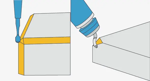
- “Break All Edges 0.13-0.25mm”: This costs nothing. The operator simply runs a chamfer mill or deburring tool along the top edges during the CNC cycle.
- Specific Chamfers: Call out precise chamfers for assembly guides (e.g., C0.5).
- Critical Surfaces: Mark surfaces that must remain sharp, so the operator avoids them.
How KaiSpeed Bridges Design Intent and Manufacturing Reality
You don’t have to memorize every machinist’s rule. At KaiSpeed, our platform is built to catch these cost drivers before a single chip flies.
We’ve augmented our KaiSpeed CNC Machining Services with an intelligent engineering review process. When you upload your CAD file:
- Automated DFM Scraping: Our system instantly flags thin walls, deep pockets, and impossible geometries.
- Human Engineering Review: Unlike algorithm-only platforms, a KaiSpeed applications engineer manually reviews your quote to suggest tolerance relaxation or design tweaks that cut cost.
- Prototyping to Production: Whether you need rapid prototyping or low-volume production, our flexible workflow scales with you.
We don’t just tell you what is wrong with your design; we tell you why it will be expensive and how to fix it.
FAQ
Q: What is the most expensive geometric feature in CNC milling?
A: The sharp internal corner. It requires Electrical Discharge Machining (EDM) or a secondary broaching step. Always design with a fillet.
Q: Can I use a stock material size to lower cost?
A: Absolutely. If your part is 0.45″ thick, design it to 0.50″ (standard stock). Face milling off 0.05″ is cheap; sourcing a custom 0.45″ billet is not.
Q: Does a black oxide finish cost more than anodizing?
A: No. Often, standard chemical finishes like black oxide are cheaper and faster than Type II anodizing, though anodizing offers better corrosion and wear resistance.
Ready to Slash Your CNC Machining Costs?
Your design is the single biggest lever you have to control cost. But you don’t have to optimize alone.
Upload your CAD file to KaiSpeed’s Instant Quoting Platform today. Let our automated DFM tools and expert engineers flag the features that are draining your budget. We’ll deliver high-precision parts at a price point that makes your project viable.