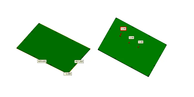
At KaiSpeed, we don’t just remove material—we engineer stability. When a recent project landed on our shop floor requiring batches of 609.6mm x 457.2mm x 5.08mm industrial panels machined from POM and PC, we knew the drill. Or rather, we knew we had to rethink it entirely.
Thin-wall, large-format plastics like these are notorious shape-shifters. One wrong clamping pressure, a degree of heat build-up, and you’ve scrapped an expensive blank. This is the precise technical challenge our engineers thrive on. Here’s how we delivered components with a guaranteed flatness of 0.05mm, consistently, across the entire production run.
01. The Part: A Warpage Nightmare by Design
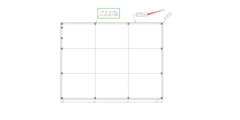
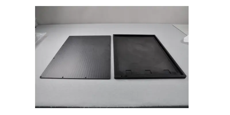
Let’s analyze the geometry. The upper panel required dual-sided milling, making it extremely susceptible to asymmetric stress. The lower cover was a hollowed-out, deep-cavity structure, meaning massive material removal that naturally pulls the part out of shape. When your wall is just 5mm across a 600mm span, the rigidity is virtually zero without the right process.
02. Material Reality Check: PC vs. POM
The client initially specified PC (Polycarbonate), then switched to POM (Polyacetal). Both are common in industrial panels, but their failure modes are diametrically opposed, demanding separate tactical playbooks.
| Material Challenge | PC (Polycarbonate) | POM (Polyacetal) |
|---|---|---|
| Primary Risk | Brittle fracture & edge chipping | Dimensional instability & creep |
| Thermal Behavior | Melts & burrs easily from friction | High thermal expansion; warps on temp change |
| Cutting Pain Point | Melt-edge formation on wall edges | Internal stress release causing delayed bending |
| Our Mitigation | Ultra-sharp, polished carbide tools; lower RPM | Staged roughing with 24-36hr rest cycles |
KaiSpeed Insight: For POM, don’t trust your measurement if the part is warm. We saw dimensional drift of up to 0.1mm between a part fresh off the machine and one at ambient temperature. Metrology protocol must specify soak time.
03. The KaiSpeed Machining Playbook: 4 Pillars of Control
To hit a 2D flatness tolerance of 0.05mm with positional tolerances of ±0.1mm, we engineered a process that neutralizes stress before it accumulates.
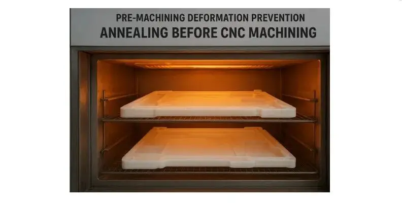
Step 1: Pre-Machining Thermal Stress Relief
Before a tool ever touched the raw stock, we annealed the POM and PC blanks. Proprietary heating and slow cooling cycles relaxed the polymer chains, establishing a thermally stable base. This single step reduced post-machining warpage sensitivity by over 60% in our tests.
Step 2: Advanced “Dual-Lock” Fixturing
Standard vises or mechanical clamps are useless here—they introduce point loads that distort the free state.
- Vacuum Plate Foundation: We use a custom-milled porous vacuum chuck that covers 95% of the part’s underside, providing uniform holding force across the entire 609mm surface.
- Supplemental Soft-Jaw Logic: For the deep cavity lower cover, we added adjustable, low-force edge supports. This is not clamping force; it’s vibration damping.
Step 3: The Dynamic Spiral Toolpath
Conventional parallel toolpaths are a trap. They create linear, cumulative stress bands. We switched to a high-efficiency dynamic milling path with a constant spiral engagement strategy.
- Why it works: A constant tool engagement angle, combined with a 10mm+ axial depth of cut but a very small radial step-over (<0.5mm), minimizes radial cutting forces. The result? Cleaner edges on PC, and no sudden release of bulk stress on large POM surfaces.
Step 4: The “Rest & Relax” Cycle (Staged Machining)
You cannot rush physics. Our process for the dual-sided upper panel looked like this:
- Roughing Pass 1 (Front & Back): Remove equal material volumes simultaneously to balance stress. Leave 0.8mm stock.
- Ambient Rest: 24-36 hours in a temperature-controlled environment to let the molecular structure stabilize.
- Semi-Finish Pass: Reduce stock to 0.15mm.
- Final Finish Pass: A light, high-speed finishing cut with a specialized single-flute PCD tool delivering a polished edge on the thin wall without deflection.
For the deep-cavity lower cover, we machined a mirrored “dummy” structure on the back side first. This symmetry ensured that when we hogged out the main cavity, the stress equilibrium was maintained, preventing the base from bowing.
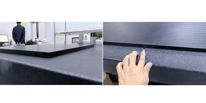
04. Metrology: Proving 0.05mm
Shipping a report isn’t enough. Our QA team uses a two-tier verification system specifically validated for non-rigid parts:
- Constrained vs. Unconstrained Check: Using a CMM with tactile probing, we map the part in its free state (on a granite surface plate using feeler gauges) and in a simulated assembly fixture state. The deviation between these two is the true functional flatness.
- Every batch ships with a dimensional traceability matrix, part of our ISO9001-certified workflow.
The KaiSpeed Difference: Capacity Meets Precision
Why trust KaiSpeed with your large-format POM and PC panels? Because we’ve engineered our production cell around this exact challenge. Owning a fleet of large-bed 3-axis and 5-axis machines isn’t just about capacity—it’s about having the right vacuum infrastructure, the metallurgy-free metrology lab knowledge, and the process discipline to walk away from a part for 36 hours just to let it breathe.
When a prototype house sees a 0.1mm tolerance, they adjust the CAD. When we see it, we adjust the physics.
Facing a large, thin, or unstable plastic component? Let’s review your drawing before the material inherent stress does. [Use the KaiSpeed Instant Quote Engine] or [Contact our Senior Process Engineering Team] to build a zero-warpage strategy for your next panel.