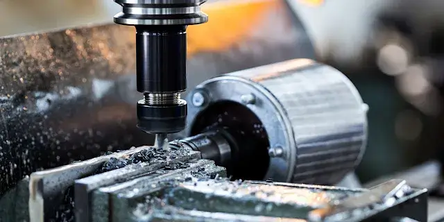
In precision manufacturing, a single machining defect can trigger costly rework, scrap, and missed deadlines. For B2B buyers and engineers, understanding these defects isn’t just technical curiosity—it’s a direct path to protecting margins, maintaining quality standards, and ensuring supply chain reliability.
At KaiSpeed, we’ve accumulated deep expertise in diagnosing and preventing CNC machining defects across thousands of projects. This guide draws on that experience to equip you with actionable insights into the most frequent problems, their root causes, and proven prevention strategies.
Understanding CNC Machining Defects: A Systematic Framework
CNC machining defects rarely stem from a single factor. Instead, they emerge from the complex interaction of five interconnected systems:
- Mechanical Transmission – machine alignment, ball screw condition, bearing wear
- Servo Control – encoder feedback accuracy, drive tuning, electrical noise
- Tooling – tool geometry, material, coating, wear state
- Programming Logic – cutting parameters, tool paths, safety heights
- Workpiece Material – material properties, internal stresses, clamping deformation
Understanding these interactions is critical for both diagnosing problems and implementing effective solutions. Below is a systematic classification of the most common defects encountered in real production environments.
Key Defect Categories and Their Root Causes
To streamline troubleshooting, we’ve organized defects into three primary categories based on where they manifest:
| Defect Category | Typical Manifestations | Primary Root Causes |
|---|---|---|
| Surface Quality Defects | Poor surface roughness, chatter marks, burrs, scoring | Tool wear, improper cutting parameters, machine vibration, resonance |
| Dimensional Accuracy Defects | Oversize/undersize parts, taper, out-of-roundness, positional errors | Machine geometry issues, thermal deformation, tool deflection, programming errors |
| Process Stability Defects | Random dimensional fluctuation, inconsistent surface finish across batches | Servo instability, electrical noise, material inconsistency, inadequate cooling |
1. Surface Finish Deterioration: When Dimensions Are Right but the Surface Is Wrong
Surface finish defects are among the most perplexing problems in CNC machining. The part measures correctly—all dimensions fall within tolerance—yet the surface fails visual or roughness specifications. In these cases, the positioning system is functioning correctly; the problem originates from dynamic instability during cutting.
Common Causes
- Tool Wear: Micro-chipping at the insert edge, flank wear, or built-up edge (BUE) formation
- Insufficient Spindle Rigidity: Excessive radial runout (over 0.01mm for precision work)
- Resonance: Spindle speed aligning with the machine structure’s natural frequency
- Inappropriate Cutting Parameters: Feed rate too high, speed too low, or depth of cut excessive
- Inadequate Coolant Flow: Poor chip evacuation leading to re-cutting of chips
Practical Solutions
- Verify Tool Condition First: Inspect cutting edges under magnification for micro-chipping. Replace worn tools immediately.
- Check Spindle Runout: Radial runout should not exceed 0.01mm for precision finishing work.
- Adjust Spindle Speed: Slight changes (±5-10%) often eliminate chatter by shifting the vibration frequency away from resonance.
- Optimize Finishing Parameters: Increase spindle RPM while reducing feed per tooth. This significantly improves surface finish in final passes.
- Ensure Adequate Coolant Flow: Proper lubrication and coolant delivery stabilize thermal conditions and aid chip evacuation.
Surface Finish Troubleshooting Quick Reference
| Symptom | Most Likely Cause | Recommended Action |
|---|---|---|
| Chatter marks (regular pattern) | Resonance or tool deflection | Change spindle speed; reduce tool overhang |
| Rough, torn surface | Built-up edge or dull tool | Replace tool; increase cutting speed |
| Scoring or gouging | Chip re-cutting or tool damage | Improve coolant flow; inspect tool condition |
| Burrs on edges | Dull cutting edge; incorrect feed | Sharpen or replace tool; adjust feed rate |
2. Dimensional Accuracy Defects: When Parts Don’t Match the Print
Dimensional defects are the most costly type of error, as they often result in complete part rejection. These can be systematic (consistent offset across all parts) or random (unpredictable variation from part to part).
2.1 Consistent Dimensional Offset
When every workpiece shows the same oversize or undersize deviation, the issue is systematic rather than random. This typically indicates incorrect machine parameter configuration.
Root Causes and Solutions:
| Error Type | Possible Cause | Diagnostic Method | Corrective Action |
|---|---|---|---|
| All dimensions offset by same amount | Incorrect tool offset or work offset | Verify G54-G59 coordinate systems | Re-establish correct offsets |
| Scaling error (consistent % deviation) | Incorrect electronic gear ratio or pulse equivalent | Command known axis movement; measure actual travel | Correct machine parameters |
| X/Y/Z positional error | Backlash compensation incorrect | Measure with dial indicator | Update backlash compensation values |
2.2 Taper Formation on Cylindrical or Long Parts
Taper errors—where diameter gradually changes along the part length—indicate geometric misalignment or structural deflection. This is especially common in turning operations on long shafts.
Diagnostic Sequence:
- Check Machine Leveling: Improper foundation can introduce torsional deformation in the machine bed.
- Verify Tailstock Alignment: Misalignment relative to the spindle centerline is a frequent cause.
- Measure Axial Backlash: Ball screw wear or excessive clearance creates linear positioning deviation.
- Assess Tool Deflection: Under heavy cutting loads, tool push-off produces measurable taper.
Solutions:
- Precision leveling using a high-accuracy spirit level (0.02mm/m or better)
- Tailstock alignment with a certified test bar
- Reduce depth of cut; apply multi-pass roughing strategies for high-strength materials
2.3 Random Dimensional Fluctuation
Size variation without a fixed pattern is rarely a programming issue. It typically indicates servo instability or external interference. Key causes include electrical noise affecting encoder feedback, improper servo gain settings, and mechanical sticking (“stick-slip”) due to inadequate guideway lubrication or incorrect ball screw preload.
Diagnostic Checklist:
- Verify encoder feedback signals and cable shielding
- Check grounding integrity; separate power and signal wiring
- Tune servo parameters to eliminate overshoot
- Inspect ball screw preload and guideway lubrication
3. Burr Formation: The Persistent Edge Quality Challenge
Burrs are among the most common and troublesome CNC machining defects. These unwanted raised edges significantly impact part functionality and assembly, and their removal often requires costly secondary operations.
Factors Influencing Burr Formation
| Factor | Effect on Burr Formation | Optimization Strategy |
|---|---|---|
| Cutting edge sharpness | Dull edges increase burr size by 3-5× | Implement systematic tool life management |
| Feed rate | Too low causes rubbing; too high causes tearing | Optimize for material and operation type |
| Exit angle | 90° exits produce largest burrs | Design chamfers or radiused exits |
| Material ductility | Higher ductility increases burr tendency | Adjust cutting parameters per material |
Prevention Strategies
- Systematic Tool Life Management: Replace tools before cutting edges dull beyond acceptable limits. At KaiSpeed, we implement predictive tool life monitoring rather than reactive replacement.
- Optimized Exit Strategy: Program tool paths to exit on less critical edges or design parts with chamfered edges at exit points.
- Appropriate Coolant Application: Proper cooling reduces material adhesion and minimizes built-up edge formation.
- Climb vs. Conventional Milling: Climb milling generally produces fewer burrs due to the chip thinning effect at tool exit.
4. Tool Wear: The Silent Productivity Killer
While tool wear is inevitable, excessive or premature wear signals underlying process problems. Understanding wear mechanisms is essential for optimizing tool life and maintaining part quality.
Types of Tool Wear and Their Causes
| Wear Type | Appearance | Primary Cause | Preventive Measure |
|---|---|---|---|
| Flank Wear | Uniform wear on tool flank | Normal abrasive wear; cutting speed too high | Reduce speed; use coated tools |
| Crater Wear | Depression on rake face | Chemical diffusion at high temperatures | Reduce speed/feed; improve coolant |
| Built-Up Edge (BUE) | Material adhesion to cutting edge | Low cutting speed; inadequate lubrication | Increase speed; use PVD-coated tools |
| Chipping | Small fractures on cutting edge | Interrupted cuts; excessive feed; vibration | Reduce feed; improve setup rigidity |
| Notch Wear | Localized wear at depth-of-cut line | Work hardening; scale on workpiece surface | Vary depth of cut; remove surface scale first |
Proactive Tool Management at KaiSpeed
At KaiSpeed, we approach tool wear as a process variable to be controlled, not an inevitable outcome. Our systematic approach includes:
- Predictive Monitoring: Using machine data to anticipate tool life rather than relying on fixed replacement schedules
- Application-Specific Tool Selection: Matching tool geometry, substrate, and coating to the specific material and operation
- Parameter Optimization: Continuously refining cutting speeds, feeds, and depths based on real-time wear patterns
5. Design-Related Defects: When the Part Was Never Machinable
One of the most overlooked sources of CNC machining defects lies not in the machine or the process, but in the design itself. Parts that violate Design for Manufacturability (DFM) principles are inherently prone to defects regardless of machining expertise.
Design Features That Trigger Defects
A comprehensive DFM guideline identifies several geometric features that consistently cause machining problems: sharp internal corners force the use of small-diameter tools, leading to vibration and poor surface finish. Deep cavities exceeding 4× the tool diameter create excessive tool overhang that allows deflection and dimensional drift. Thin walls (under 0.8mm for metals) deform under cutting forces, making tolerance holding nearly impossible. Blind holes deeper than 3× diameter trap chips and increase the risk of tool breakage. Finally, over-specified tolerances on non-functional surfaces unnecessarily drive up costs without adding value.
DFM Optimization Guide
| Design Issue | Risk | Recommended Solution |
|---|---|---|
| Sharp internal corners | Tool vibration, poor finish | Minimum internal radius ≥ 0.5mm (larger preferred) |
| Deep, narrow cavities | Tool deflection, dimensional drift | Depth ≤ 4× cutter diameter; consider splitting part |
| Ultra-thin walls (metal < 0.8mm) | Deformation under cutting forces | Add ribs; use stress-relieved material |
| Deep blind holes (> 3× diameter) | Chip packing, tool breakage | Use peck drilling cycles; consider through-holes |
| Over-specified tolerances | Unnecessary cost, inspection complexity | Tight tolerances only on critical mating features |
Defect Prevention Framework: From Reactive to Proactive
Preventing defects is far more cost-effective than detecting and reworking them. Our approach at KaiSpeed integrates several layers of defense:
Layer 1: Design Review and DFM Optimization
Before any metal is cut, our engineering team reviews part designs for manufacturability. DFM validation alone can prevent 30–50% of potential machining defects.
Layer 2: Process Planning and Parameter Optimization
Optimal cutting parameters—speeds, feeds, depth of cut, and tool path strategy—are determined based on material properties, tool characteristics, and machine capabilities. Simulation tools verify tool paths before production begins.
Layer 3: Predictive Tool Management
Rather than running tools to failure (which damages parts) or replacing them prematurely (which wastes resources), we use data-driven approaches to predict optimal replacement intervals.
Layer 4: In-Process Monitoring and Inspection
Real-time monitoring of machine performance, combined with in-process inspection using precision measuring instruments, catches deviations before they result in defective parts.
Layer 5: Post-Process Verification
Coordinate Measuring Machines (CMMs) verify dimensional accuracy to micron-level precision, while surface profilometers confirm finish quality requirements.
The KaiSpeed Advantage: Engineering-Led Defect Prevention
Defects in CNC machining aren’t random events—they’re predictable consequences of specific root causes. By understanding these causes and implementing systematic prevention strategies, manufacturers can dramatically reduce scrap rates, improve delivery reliability, and lower total cost of quality.
At KaiSpeed, we’ve built our entire production system around this principle. From rigorous DFM reviews and predictive tool management to multi-layer quality control, our approach ensures that your critical components arrive right the first time, every time.
Don’t let machining defects compromise your product quality or production schedule. Partner with a machining service that understands defect prevention at the engineering level.
Contact KaiSpeed today to discuss your next precision machining project, and experience the difference that systematic quality control makes.