Impellers are critical components used in turbomachinery systems such as pumps, compressors, turbochargers and aerospace engines. Their function is to transfer rotational energy into fluid motion, making them essential in many high-performance industrial systems.
However, machining impellers is one of the most challenging tasks in precision manufacturing. The combination of twisted blade geometries, narrow flow channels, and tight aerodynamic tolerances requires advanced machining technologies.
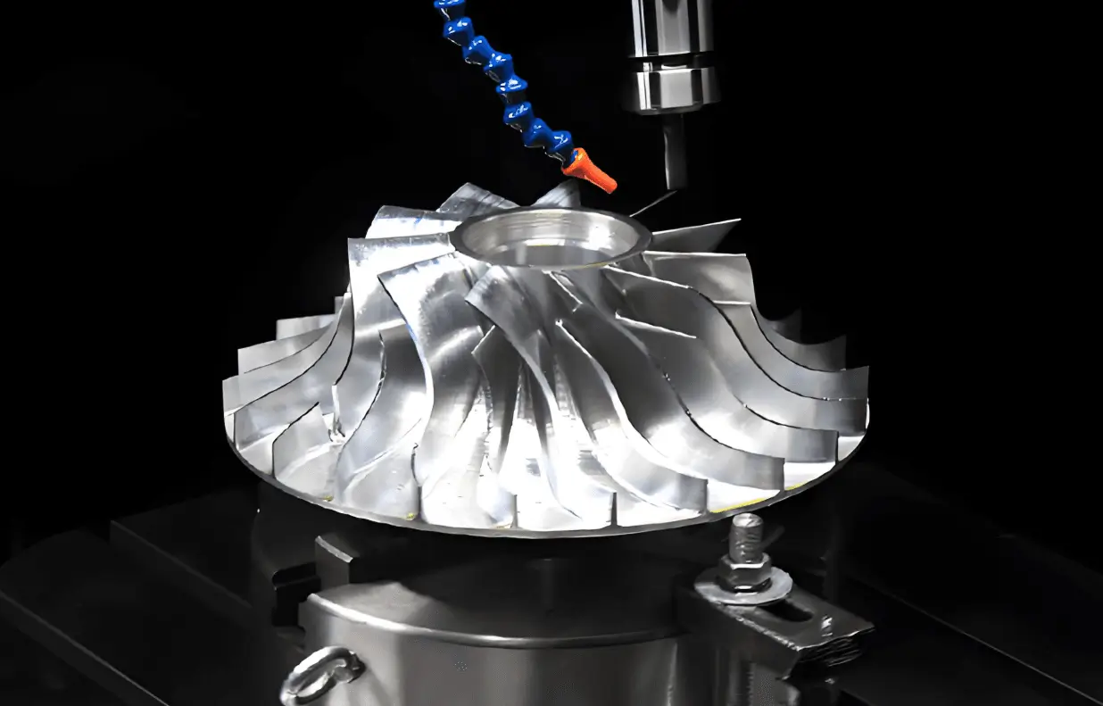
Today, 5-axis CNC machining has become the preferred solution for producing high-precision impellers. This technology allows manufacturers to machine complex curved surfaces in a single setup while maintaining exceptional dimensional accuracy and surface finish.
In this guide, we will explore:
- What impellers are and how they work
- Why impellers are difficult to machine
- The advantages of 5-axis CNC machining
- Materials used for impeller manufacturing
- Advanced machining techniques
- A real engineering case study from KaiSpeed
What Is an Impeller?
An impeller is a rotating mechanical component designed to move fluids by converting rotational energy into kinetic energy.
Impellers are commonly found in:
- centrifugal pumps
- compressors
- turbochargers
- aerospace turbine engines
- chemical processing equipment
Basic Impeller Structure
Most impellers consist of several key elements.
| Component | Function |
|---|---|
| Hub | Central structure connecting to the shaft |
| Blades | Accelerate and guide fluid |
| Shroud | Outer plate improving flow efficiency |
| Backplate | Structural support |
The aerodynamic blade design plays a crucial role in determining system performance.
Why Impellers Are Difficult to Machine
Impellers present several unique manufacturing challenges.
1. Complex Blade Geometry
Impeller blades are typically twisted three-dimensional surfaces. These complex curves require simultaneous multi-axis tool motion.
Traditional 3-axis machining cannot efficiently produce such geometry.
2. Limited Tool Access
The narrow spacing between blades restricts cutting tool access, especially in closed impellers.
This makes machining and finishing extremely challenging.
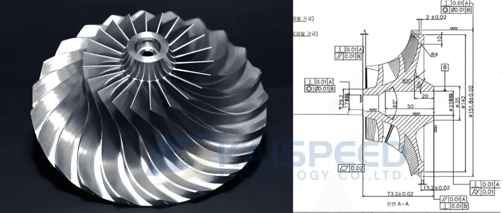
3. Tight Tolerances
High-speed turbomachinery components require strict dimensional control.
| Feature | Typical Tolerance |
|---|---|
| Blade profile | ±0.02 mm |
| Runout | ≤0.01 mm |
| Surface finish | Ra 0.8–1.6 μm |
Even small deviations can significantly affect aerodynamic performance.
Why 5-Axis CNC Machining Is Ideal for Impellers
Modern impeller manufacturing relies heavily on simultaneous multi-axis machining.
Compared with traditional machining, 5-axis systems offer significant advantages.
| Feature | 3-Axis CNC | 5-Axis CNC |
|---|---|---|
| Setup | Multiple setups | Single setup |
| Tool access | Limited | Full access |
| Accuracy | Moderate | Extremely high |
| Surface finish | Average | Superior |
Benefits of 5-Axis Machining
Single-Setup Manufacturing
The part can be machined from multiple angles without repositioning.
Improved Surface Finish
Continuous tool orientation ensures smoother blade surfaces.
Higher Efficiency
Fewer setups reduce machining time and cumulative errors.
For complex turbomachinery components, advanced 5-axis CNC machining has become the industry standard.
Materials Used for Impeller Machining
Material selection depends on operating conditions such as temperature, corrosion, and rotational speed.
| Material | Advantages | Typical Applications |
|---|---|---|
| Aluminum alloys | Lightweight | Aerospace prototypes |
| Stainless steel | Corrosion resistant | Pumps |
| Titanium | High strength-to-weight | Aerospace turbines |
| Inconel | High temperature resistance | Gas turbines |
| Bronze | Excellent wear resistance | Marine pumps |
Each material requires specific machining strategies to maintain precision and tool life.
The KaiSpeed Engineering Workflow for Impeller Machining
Producing high-performance impellers requires a systematic engineering approach.
At KaiSpeed, we use a closed-loop workflow integrating CAM programming, digital simulation, precision machining and inspection.
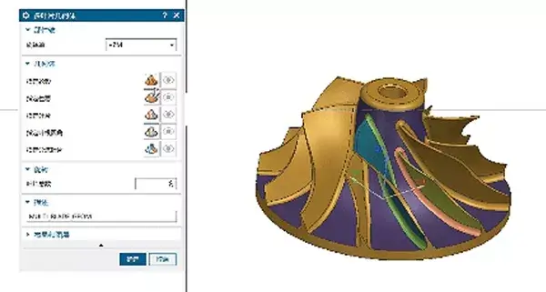
1. Advanced CAM Programming
Modern CAM systems include specialized modules designed specifically for impeller machining.
Our engineers begin by defining key geometry features:
- hub surface
- blade profiles
- root radius
- shroud geometry
The software then generates optimized toolpaths for roughing and finishing.
Two Key Milling Methods
| Method | Description | Application |
|---|---|---|
| Point Milling | Ball-nose tool machines blade surfaces | Blade finishing |
| Flank Milling | Cutter side engages hub surface | Flow channels |
Point milling ensures precise blade surfaces, while flank milling improves efficiency when machining hub areas.
2. Digital Twin Simulation
Before machining begins, the entire process is simulated in a virtual environment.
Simulation helps engineers:
- detect tool collisions
- verify holder clearance
- optimize tool orientation
- prevent thin-wall deformation
This digital twin approach significantly reduces machining risks.
3. In-Process Monitoring
Our machining centers include probing systems and laser tool setters.
After roughing operations, the probe measures stock distribution and recalibrates the coordinate system if necessary.
This ensures maximum dimensional accuracy during finishing passes.
Case Study: High-Speed Centrifugal Compressor Impeller
A recent KaiSpeed project involved machining a high-speed centrifugal compressor impeller for an aerospace client.
Project Specifications
| Parameter | Specification |
|---|---|
| Material | AL7075-T6 |
| Diameter | 194 mm |
| Blade Count | 12 twisted blades |
| Minimum spacing | 10.5 mm |
| Surface roughness | Ra 0.8 μm |
| Quantity | 8 pieces |
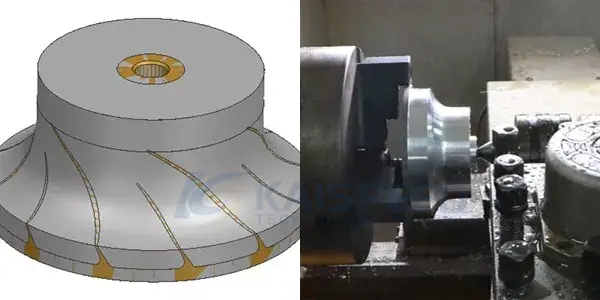
Step 1 – Precision Turning
The manufacturing process began with CNC turning.
The following features were machined:
- outer diameter
- top and bottom surfaces
- central bore
This step established a perfectly concentric reference axis.
Step 2 – 5-Axis Rough Machining
The prepared blank was transferred to a high-speed 5-axis machining center.
Using a bull-nose cutter, we opened the flow channels while leaving a 0.5–1 mm finishing allowance.
Step 3 – Blade Finishing
The blade surfaces were machined using small ball-nose end mills in simultaneous 5-axis motion.
Key parameters included:
- spindle speed above 15,000 RPM
- optimized step-over distance
- constant tool engagement
This allowed us to achieve the required Ra 0.8 μm surface finish directly from machining.
Step 4 – Flow Channel Finishing
After blade machining, the hub and flow passages were finished using similar toolpath strategies.
Smooth blade-hub transitions ensure optimal aerodynamic efficiency.
Step 5 – Inspection and Balancing
After machining, the impellers underwent comprehensive inspection.
Quality control included
- CMM dimensional inspection
- surface roughness measurement
- dynamic balancing
These steps ensured stable operation at high rotational speeds.
Cost Factors in Impeller Machining
Impeller manufacturing cost depends on several factors.
| Factor | Impact |
|---|---|
| Material | Titanium and Inconel increase cost |
| Geometry | More blades increase machining time |
| Tolerance | Higher precision increases cost |
| Volume | Larger production lowers unit cost |
Although 5-axis machining has higher machine hourly rates, it often reduces total manufacturing cost by eliminating multiple setups.
Design Tips for Machining Impellers
Engineers can improve manufacturability by following these guidelines.
Avoid extremely thin blades
Thin structures increase deformation risk.
Provide adequate blade spacing
This ensures sufficient tool access.
Use smooth geometric transitions
Sharp corners should be avoided.
Working with experienced manufacturers early in the design stage helps optimize performance and cost.
Why Engineers Choose KaiSpeed
KaiSpeed specializes in manufacturing complex precision components for demanding industries.
Our capabilities include:
- advanced multi-axis machining centers
- experienced process engineers
- rigorous quality inspection
- fast prototyping and production
Through our precision CNC machining services, we support aerospace, robotics and energy industries with high-performance components.
We also provide a full range of surface finishing options for precision parts to meet demanding functional and aesthetic requirements.
FAQ
What is impeller machining?
Impeller machining refers to the manufacturing process used to produce rotating blades used in pumps, compressors and turbines.
Why is 5-axis machining used for impellers?
5-axis machining allows tools to access complex curved blade surfaces from multiple angles, enabling higher accuracy and better surface finish.
What tolerance is required for impellers?
Typical CNC machined impellers require tolerances around ±0.02 mm and surface roughness between Ra 0.8–1.6 μm.
Ready to Start Your Impeller Project?
Whether you need prototype impellers or production turbomachinery components, KaiSpeed offers reliable engineering support.
Upload your CAD model today and receive a fast quote and professional DFM analysis from our engineering team.